The following image can be seen in this October 1998 issue. The green bar at the bottom of the picture gives us an illusion. Although the ink values ​​on the entire bar are set the same, the printed results are different on the left and right sides. We specifically used the scanner to test the entire color bar. As a result of the test, the right side of the data is 3% more than the left side; 10% more product; 15% more yellow. But in the original TIFF file, the two sides of the data are the same, and the same results are the same. Why did it produce such results on the prints?
First of all, we look at the actual situation in the offset printing process.
If a document is output to a film and it is transferred to a newspaper, the effect of printing must be less than the effect we use in a sheet-fed commercial printer. If printed in this magazine, the effect will be somewhere in between. If we send digital files directly to color copiers, it may be more effective than any other approach to the effects of newspaper printing. If dye-sublimation or ink-jet printers are used, the results may be different, as if we had encountered a large-scale copy.
This phenomenon is generally called dot gain. Somewhere in the printing process must be considered. If we do not consider this; then the final printing effect may surprise us, that is, the result will be very unsatisfactory.
There is an illustration of a female face on this page. We can use it to illustrate the problems we face. This picture comes entirely from the same digital file and is printed on almost identical devices. We scan and enlarge the printed results, and we can see that the dot shape of the right half of the face is much better than that of the left half face. In the actual viewing process, because the dots are too small, the observer is generally not aware. However, since the structure of the halftone dots is different, the effect of the image of the left half of the face seen by the observer is different from that of the image of the right half of the face.
How to determine this parameter?
We live in an age of electronic publishing. We are accustomed to computers, plate-making equipment, and film recorders. They all have stable working conditions and they do not change every day.
Unfortunately, in the final stage, there is a big hurdle. The printer uses a lot of ink to copy the content, and during the printing press work, these inks come in doubt with doubts about the color and time in a series of drums and printing. Changes in the edition.
At very high speeds, the plate hits the blanket cylinder and the ink is transferred to the blanket. The performance of the blanket is largely related to its degree of aging and its tightness. The blanket then transfers the ink back to the paper. The paper receiving capacity is related to the printing speed, humidity and temperature at that time. The printing performance on the same sheet of paper is not exactly the same as on the other side.
The pictures presented below have appeared in six different publications. Although their actual sizes are large at the time of publication, their relative dimensions are correct in this article. And, they are all output from the same digital file. The same scan settings were used when these images were reprinted for publication in this article. Although these images were re-adjusted to avoid problems caused by re-screening, they did not change substantially in relative color. At the periphery of each image, we retain the original paper color. Figures A, C, E have 150 lines and the others are 133 lines.
We actually hope to see that their copying effects are basically the same. But as we have seen, they are not the same. Why some copying situations can get the expected results, but others do not? Here we explain the reasons for this different effect.
Picture F was published in this issue in January 1997. A few months later, it appeared with the effect of Picture D in our later sister publication "Computer Artist" (Computer Artist). Picture D and Picture F are not exactly the same, but they are very close. They use the same film and printer for printing. Obviously, the printing process is well controlled. The 1 highlight part in the D chart appears brighter, and the background of the D and F charts may be due to the fact that the brightness of the paper used in the D chart is brighter.
Picture A appears in the GATF magazine founded by the GATF Association of the printing industry in the United States. The effect of picture F is basically similar to that of picture D, but the effect is darker and flatter, so it expands more in printing dots. This may be the reason it uses a finer network cable.
Picture E is published in a European magazine. Of the six images, it was the only one to print using a sheet-fed press. The dot gain of this type of printer was generally smaller than that of many web-based web presses. Also, unlike the United States, Europe People are accustomed to using positive-working platemaking methods, which have inhibitory effects on dot gain, although other problems may arise.
So no surprise, this image is the brightest of the six. Does it mean that this image is our most satisfactory result? of course not. Although some of the bright effects are good, the yellow version of this image is too weak.
Picture C is not printed in the United States. It was published in South America. Like E, it was far from the other images. Its effect was dark and red.
Picture B is the result of a recent issue of the magazine. Its effect is brighter than most of these images, because its imagery uses a direct plate-making method without the use of a film as an intermediate link. This process reduces dot gain, which may be the same as the color change in picture E.
Then, looking back, let's look again at the two images of the two faces of the face image mentioned at the beginning of the article.
Factors affecting the printing effect
As we mentioned earlier, the dot structure in the right half of the face is clearer and better reproduced from the left. The dot expansion on the left takes place in the most traditional form. The dot penetrates into the paper and loses clarity and looks wider. This gave us the illusion that the left picture is darker than the right picture.
Not only that, the left picture is also reddish, in part because the dominant magenta and yellow dots in the skin tone become larger. The cyan dots used to suppress the red are actually lost. If we look at it with a magnifying glass, we can see some blue dots on the right, but we can't see it on the left. Therefore, the left half is the redest image effect. So from the six pictures, the redest C picture. The right half comes from B. Compared with the traditional method of using a film to expose the plate, the dots formed by the plate making method of the direct image plate have a high definition.
We also need to explain the use of the printing machine in Picture C: In addition to the problem of network expansion, printing machines have difficulties in retaining the brightest screens. Therefore, in the printing process, the cyan media outlets have lost. This phenomenon indicates that the printing machine should use a thicker screen number when printing jobs. `This also shows that there are many problems that seem to be caused by the expansion of outlets. It is not really a fact.
Similarly, the darker effects produced by the A-picture may be due to dot gain, or because the magenta ink used by the press is somewhat dirty and red. It is more likely that the printing units will be caused by the unevenness in the transfer of color inks and yellow inks. It is easy to understand that printing with a four-color printing press is better than printing on a sheet-fed press. Moreover, it is not uncommon for the dot gain rate to be different for each color ink.
If the printing results do not reach the best results, the reason is probably the above. Or, simply because of random reasons, it may be because the humidity on that day is too high, or if you forgot to clean a printing unit according to regulations, or if the printing press is not working at the normal speed, or because it is in this magazine. The image does not represent the overall level of this printing. More likely, and finally possible, in the course of the work of this image, the printing workers do not have good control.
This may be confusing for everyone, but only a handful of skilled workers in the printing industry will use the high magnification magnifiers often found in their pockets to properly analyze all problems that affect quality. On the other hand, most people can only see the difference between light and dark images, but the difference between light and shade is not necessarily caused by any factor. If you think it is caused by dot gains, then please control it carefully.
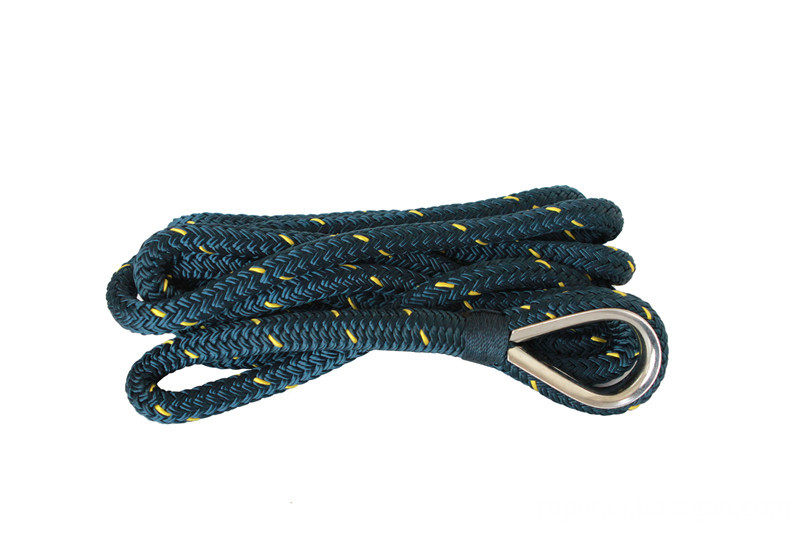
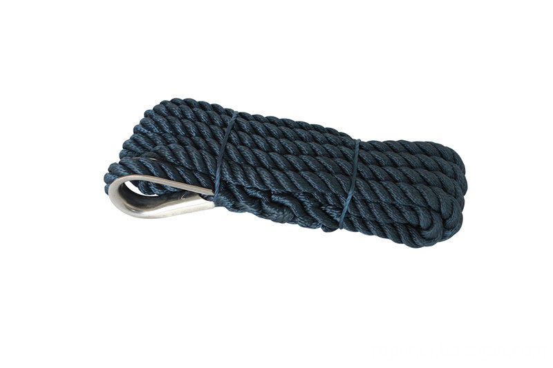
The Anchor Line are designed to provide optimal protection for boats and watercraft. Every item we offer has been carefully selected for its durability and performance in harsh marine conditions. This premium anchor line is lightweight and floatable, with a tough solid braid construction, and a stainless steel thimble for simple, secure anchor attachment. MFP (Multifilament Polypropylene) anchor line is stronger and softer than traditional polypropylene. It`s more economical than nylon or polyester, with the soft hand feel of nylon at a lower price point. It`s lighter weight than its nylon and polyester counterparts, and will float when thrown in water. MFP holds knots well, and has high abrasion resistance. It also resists chemicals, rot, and mildew. This solid braid anchor line is round, flexible and smooth.
Features
·3/8`` x 100` premium multifilament polypropylene (MFP) solid braid anchor line with stainless steel thimble on one end
·MFP is lightweight and floatable, with low stretch and minimal water absorption; it resists saltwater, gas, oil, acids, abrasion, mildew and UV
·Working load limit: 250 lbs. / Breaking strength: 1290 lbs.
·Solid braid is smooth and flexible, with a structure that resists kinks or hockles
·Limited Lifetime Warranty


FAQ:
Q: How about payment terms?
A: 30% TT deposit + 70% TT against the B/L copy within 3 days.
Q.:What about the lead time?
A: We need 3-7 days to get the samples ready, for bulk goods, it will cost 15-60 days,up to the quantity.
Anchor Line
Anchor Line,Anchor Rope,Premium Nylon Anchor Line,Double Braided Anchor Line
ROPENET GROUP CO.,LTD , http://www.cnparacord.com