1 System plan introduction
This system uses the AT89S52 microcontroller with MCS51 architecture. The AT89S52 is a low cost, low power, high performance CMOS 8-bit microcontroller with 8 KB of system programmable Flash memory. To use the AT89S52 to read and write SD cards, first determine the communication scheme between them. The SD card has two optional communication protocols: SD mode and SPI mode. SD mode is the standard read/write mode of SD card. To select this mode, you need to select MCU with SD card control interface or additional SD card control unit. SPI mode completes communication between SD card and main controller through SPI bus. The AT89S52 does not have an integrated SD card controller. In order not to add additional SD card control unit hardware costs, this design uses the SPI communication mode of the SD card. Although the AT89S52 does not have an integrated SPI interface module, the SPI interface timing can be simulated in software.
Another problem to be solved is the level matching of the SD card with the AT89S52. The logic level of the SD card is equivalent to the TTL level standard of 3.3 V, and the logic level of the AT89S52 is 5 V CMOS level.
There are two principles for solving the level matching problem: one is the minimum value of the output level of the output level device, which should be greater than the lowest voltage value that the receiving level device recognizes as the high level; the other is the output level device output. The maximum voltage value of the low level should be less than the highest voltage value that the receiving level device recognizes as low.
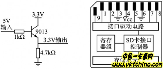
Considering that the SD card is in SPI mode, the data transmission is unidirectional, so that the transistor can be used to transfer data to the SD card. The basic circuit is shown in Figure 1. And in SD
The card can be directly connected when transmitting data to the MCU, because the level between them just meets the above-mentioned level compatibility principle, which is economical and practical. This solution requires dual power supply, one 5 V power supply and one 3.3 V power supply.
2 AT89S52 and SD card interface circuit design
2.1 SD card interface specification
The SD card works at 2.7~3.6 V. Figure 2 shows the structure and pinout of the ordinary SD card. Table 1 lists the definition and function description of each pin in SPI mode. The host and the SD card communicate with each other through instructions.

Figure 1 Level conversion circuit Figure 2 SD card structure
2.2 interface circuit design
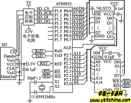
The AT89S52 has 256 bytes of RAM. Since the SD card data is read and written in blocks, and each block is 512 bytes, it is necessary to expand one RAM on the minimum system of the microcontroller. The RAM chip selected for this system is HM62256 with a capacity of 32 KB. The system hardware circuit is shown in Figure 3.
Table 1 SD card pin definition in SPI mode


Figure 3 system hardware schematic
3 software design
3.1 FAT16 file system

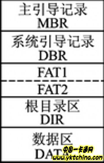
Figure 4 Schematic diagram of FAT16 storage structure
The storage structure of the FAT16 file system is shown in Figure 4.
The Main Boot Record (MBR) is located in the zeroth sector of the physical disk. There is a Disk Partition Table (DPT) in the MBR, and the DPT records the relative offset of each logical partition. The SD card does not support multiple partitions. There is only one partition in one SD card. Therefore, only one partition entry is occupied in the DPT on the SD card. The DOS Boot Record (DBR) is located in the 0th sector of the logical partition of the disk and is the first sector accessible by the operating system. It contains a partition parameter called BPB (Bios Parameter Block). Record Form. BPB records important parameters such as the root directory size, FAT number, disk media description, and allocation unit size of the partition.
The DBR is followed by a FAT (File Allocation Table), which records the storage location of the file on the disk. In Windows systems, the unit of file storage is clusters rather than bytes. A file is not stored continuously in a certain area of ​​the disk, but is often divided into several segments and stored like a chain. The FAT table records the starting cluster number, subsequent cluster number, and terminating cluster number for each file. Each entry in the FAT table corresponds to one cluster in the data storage area. Due to the importance of the FAT table for file management, the FAT table has one backup.
The DIR is the root directory area, and immediately after the second FAT table (FAT2), attributes such as the starting cluster number and size of each file in the root directory are recorded. The operating system combines the FAT table to locate the file according to the starting cluster number and size of the file in the DIR.
LED Plastic Pot Feature:
1. Polyethylene (PE) is a kind of thermoplastic material, not easy to broken, suitable for long time delivery
2. Non toxic, safe for human healthy
3. Rechargeable battery and remote control
4. Multi-colors change & color selection
5. Anti UV & waterproof
6. Adopt the EPISTAR led chip to ensure the color quality and life time
7. Certificate: CE, ROHS, etc
8. Warranty: 1 year
Bar, nightclub, golf club, disco, KTV, bistro, patio, pub, hotel, restaurant, cafe, coffee shop, tea house, plaza, garden, entertainment park, amusement park, home, villa, swimming pool, wedding, party, events, decoration, design, project, rental/hire.
Led Plant Pots,Led Flower Pots,Led Garden Pots,Led Lighted Flower Pots
KIWA ELECTRONIC (HK) INDUSTRIES CO.,LTD , https://www.kiwahk.com